Conversion Process - Electrical - Wheel speed sensor mounting (for Cycle Analyst).....
In order to setup the "Cycle Analyst" (I have a high voltage ?High Current version) you must amongst other things provide it with a signal of the vehicles wheel rotation (in my case one revolution = 1740mm of movement - the wheels circumference...). The "Cycle Analyst" uses this signal to calculate the vehicles speed and distance travelled and in turn working out the watts per distance travelled These are design for use on electric bikes and hence are shipped with a magnet and reed switch arrangement suitable for bike spokes. I looked at a number of options and ended up with two possibilities. The first was to mount a thin button magnet on the inside of the rear steel rim with the reed switch fixed to a bracket mounted off the backing plate. This would be fairly easy as the 12" factory steel rims are very dished (+40 offset). The second option was to fix the thin button magnet on to the actual rear brake drum with the reed switch mounted off the backing plate. This is more difficult but allows simpler changing of wheels and rim which I plan to do in the future. So I decided to go with the second option.....

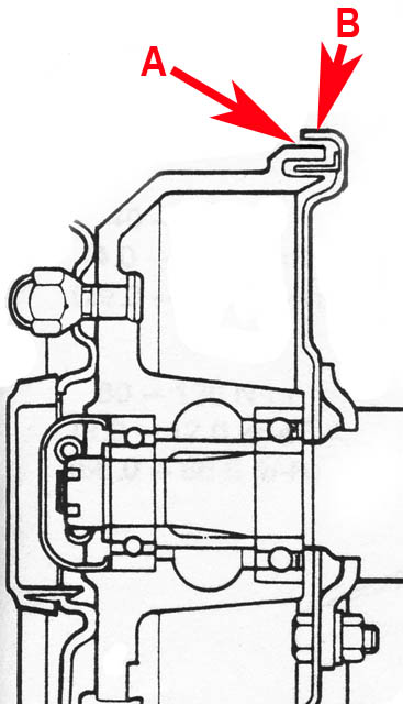
The actual case iron brake drums on the Mightyboy have lips ("A") that allow for the drilling and tapping of two small holes
See "A" above - this does not affect the safety of the drum as these lips only serve as a seal to keep out moisture and dirt
Two additional holes ("B") are drilled and tapped into the back plate to secure the reed switch mounting bracket
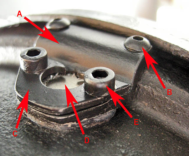
The small button magnet is sandwiched to the drum as shown.....
A - main part of the holder (main plate)
B - two securing screws (2mm) - these hold the main plate to the drum lip....
C - the top retaining plate (has a smaller hole then the magnet OD)
D - the thin button magnet in position
E - two short screws (2mm) that hold the top retaining plate ("C") to the main part of the holder ("A")
THESE DO NOT SCREW INTO THE BRAKE DRUM - ONLY THE MAIN PLATE
Plates are Aluminium - Screws are S/S
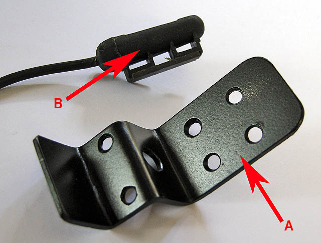
Bracket ("A") to hold the reed switch sensor ("B")
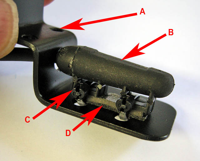
Sensor bracket ready for mounting on to the backing plate
A - holes for screws to secure the bracket to the backing plate
B - reed switch sensor
C - two cable ties
D - quality double sided foam tape (used for holding body mounting onto panels)
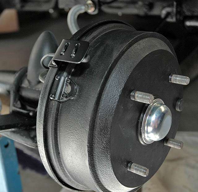
All mounted and tested
The small amount of weight added to the drum should not cause any balance issues.....
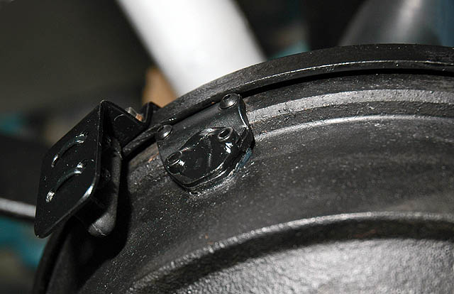
A small amount of "manifold" RTV silicone (high temperature silicone) was used in the final assembly to seal the open areas from moisture and dirt....
<- Previous Page | Next Page ->
Back to "Conversion Process - Electrical" Index Page