Conversion Process - Electrical - Wiring diagram - Tidying some loose ends.....
These first two photographs follow
on from the details provided on the
Charger
plug and safety interlock page
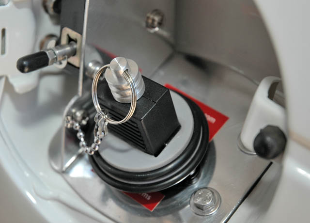
The finished IEC socket cap.....
Made by turning up a scrap bit of PVC to the right diameter
Then cutting a rectangular hole in the centre to accommodate an IEC plug body (made as a press fit)
This is glued in with 24 hr epoxy....
A small bit of turned Al rod was used at the old cord end of the plug
to provide a fixing point for the light retaining chain.....
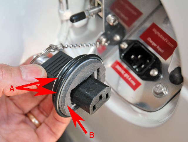
A - Two "O" rings are used (fit into grooves turned into the outer diameter) as a bumper to protect the paint work when the cap is removed for charging
B - 3mm closed cell foam is glued to the PVC face - this overlaps and compresses slightly against the outside lip of the IEC socket
providing a moisture and dust seal.....
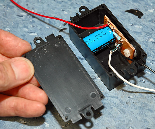
This is the finished brake light warning test circuit as detailed on the Wiring diagram - Cabin page
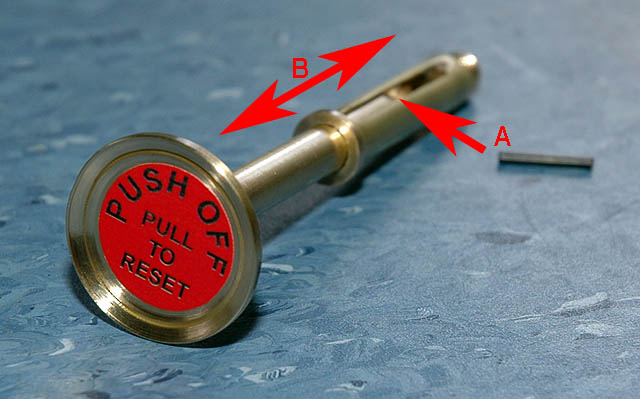
What's this?
The emergency shut off (in motor bay area) and combined reset rod (see below) ended up being too tall and hit the bonnet!
SO, I had to turn up a telescopic arrangement as shown above.
The roll pin (A) fits into the hole in the shaft and acts as a retaining stop.
The knob can slide freely up and down (B)
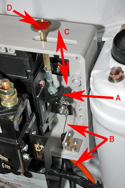
The sheathed cable wire (B) (a flexible bike gear change cable NOT a choke cable) is connected to the circuit breaker arm (A) - the other end is attached to a large red knob (marked "Emergency Off - PULL") in the cabin area (not shown). When pulled it "drops" the circuit breaker. The telescopic movement (C) allows the rod to drop. Lifting (D) resets the circuit breaker.
When working in the motor bay, pushing (D) downwards acts as an emergency shut off as well.....
Note: A small IP65 box (shown on next page), fitted with a rubber gasket, will cover the knob and slotted hole when not in service - keeping the unit waterproof.

The finished IEC socket cap.....
Made by turning up a scrap bit of PVC to the right diameter
Then cutting a rectangular hole in the centre to accommodate an IEC plug body (made as a press fit)
This is glued in with 24 hr epoxy....
A small bit of turned Al rod was used at the old cord end of the plug
to provide a fixing point for the light retaining chain.....

A - Two "O" rings are used (fit into grooves turned into the outer diameter) as a bumper to protect the paint work when the cap is removed for charging
B - 3mm closed cell foam is glued to the PVC face - this overlaps and compresses slightly against the outside lip of the IEC socket
providing a moisture and dust seal.....

This is the finished brake light warning test circuit as detailed on the Wiring diagram - Cabin page

What's this?
The emergency shut off (in motor bay area) and combined reset rod (see below) ended up being too tall and hit the bonnet!
SO, I had to turn up a telescopic arrangement as shown above.
The roll pin (A) fits into the hole in the shaft and acts as a retaining stop.
The knob can slide freely up and down (B)

The sheathed cable wire (B) (a flexible bike gear change cable NOT a choke cable) is connected to the circuit breaker arm (A) - the other end is attached to a large red knob (marked "Emergency Off - PULL") in the cabin area (not shown). When pulled it "drops" the circuit breaker. The telescopic movement (C) allows the rod to drop. Lifting (D) resets the circuit breaker.
When working in the motor bay, pushing (D) downwards acts as an emergency shut off as well.....
Note: A small IP65 box (shown on next page), fitted with a rubber gasket, will cover the knob and slotted hole when not in service - keeping the unit waterproof.
<- Previous Page | Next Page ->
Back to "Conversion Process - Electrical" Index Page