Using MightyBoyEV - Keeping it on the road.....
With the car now fully in use and the kilometres starting to clock up it's time to look at keeping it on the road.
I now have spare parts that include:
Alltrax controller
Main contactor
Main circuit breaker and fuses
Battery charger
Solid state relays
Brush set for ADC motor
One of the joys of living in Oz is that the majority of these parts are not available here, thus if you rely on the vehicle you must stock your own spare parts.
Maintenance, apart from standard things like tires, brakes, wheel bearing ,CV joints etc, mainly consists of taking care of the batteries and there connection to the motor.
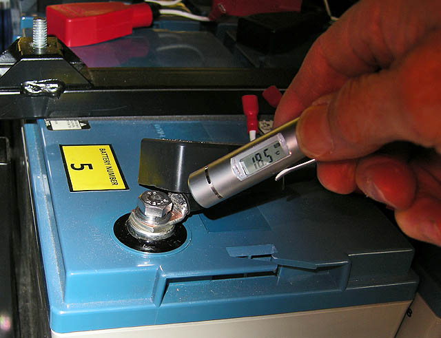
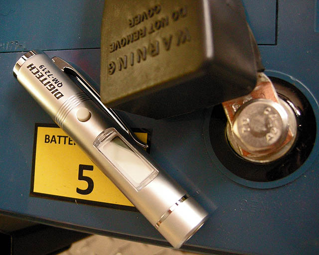
The biggest problem, especially on a lower voltage conversion such as this project, is maintaining quality low resistance connections. Correctly prepared connections, as discussed in other areas of this site, is extremely important. Periodic checking of bolt/spring washer tensions on batteries and other high current connections is critical. One tool that can help pick a potential connection problem is the use of a portable Infra Red (IR) point and shoot thermometer as shown below.

Simply lift the insulating boot and push the button..... Any hot spots can easily be picked

These are readily available for less then $50 (Oz)
Next Battery Monitoring
The other two thing that will be added to the battery pack on MightyboyEV are:
Hi-Lo battery alarm (one for each battery)
High temperature alarm (one for each battery)
Note that both these alarms will be audio alarms only and not part of the interlock chain. This is by design as I want to notify the driver of a developing problem before it becomes a risk. Adding such alarm conditions to the interlock chain could also be dangerous - one does not want the vehicle to "cut-out" on the road or pulling into traffic.....
"Hi-Lo" Alarm Details
Background; I was originally
going to use Rudman regulators (series regulators) on each battery. But
with the Delta-Q 72 volt charger and the algorithm I am using (42 for these
Powersonic batteries) the charger in theory largely takes care of the balancing
in its finishing (or pulse phase etc). This basically puts a higher
voltage (but low current) pulses across the series string (In my
case just 6 batteries). It does seem to work very well (to my
amazement!) and the batteries seem to stay are very close in voltage. So…..
Putting a regulator in set to say 14.1 volts would not allow this higher
equalising pulse to operate (2.7 volts per cell or 16.2 volts per battery).
So assuming the charger does
equalise correctly, my dilemma is the “Lo” to “Hi” range needs to be fairly wide
in order to be in a non-alarm condition - this would be about 10 to 16.2 volts
(10 volts representing the worst case sag voltage per battery under my
highest current draw (just under 400 Amps on this 72 volt pack) and 16.2 volts
representing the maximum pulse voltage during the “finishing” or “Pulse” stage
of the Delta-Q 72 volt cyclic charger). So I guess like all things it’s a
compromise. Can’t do much about the “Hi” end but maybe bring the “Lo” end up to
say 11.5 volts and use it as an indicator of “lead foot syndrome” ….. I
think this will still act as a basic “battery string out of balance alarm”
(the 11.5 volt level being more useful) and bring it to the attention of an
unaware driver – hopefully preventing too much damage to the pack.....

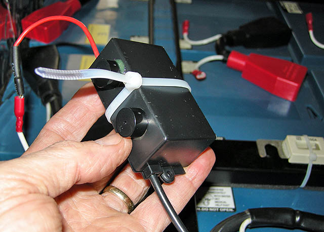
Making six simple dual voltage comparators
Didn't bother making up a PCB as the circuit is basic and stitch wiring is fine given they will be potted anyway.....

Test Unit - Mainly to check to "Hi" level setting during charging conditions.....
Continued on following page......